1 Bit Full Adder Circuit Diagram
Adder bit circuitverse Adder carry circuit sum logic implementation output combinational simplified two outputs electronics tutorial both shows below figure Embedded developer » blog archive 1-bit full adder with carry
Adder (electronics) - Wikipedia
Adder bit logic circuit indie electronics Performing addition on ibms quantum computers — quantum computing uk Explain full adder circuit using pla having three inputs, 8 product
Adder cmos soi
Adder bit logisim circuit using cs build cornell labs lab1 courses edu create re ta sub askAdder vhdl circuits ckt What is half adder and full adder circuit?Adder circuit construction logic binary circuits sourav gupta qiskit.
Adder vhdl 8bit simulate compile waveform verifyFull-adder circuit, the schematic diagram and how it works – deeptronic Adder logic logisim sumador npn bjtVhdl tutorial – 10: designing half and full-adder circuits.
Adder bit using circuit four half implementation watson circuits adders latech edu
Full adder conbinational circuitI made a 4-bit calculator in fallout 4 : pcmasterrace Logisim adder circuit bit subtractor digital fulladder technologyAdder ripple carry bit circuit logic verilog code digital output combinational sum delay gates propagation start so begingroup.
Proposed 1-bit full adder circuit.Adder bit circuit subtractor ripple carry diagram logic using project digital computing learn let build its indie electronics Download 4 bit adder circuit stick and logic diagramAdder circuitverse ghosh circuits.

Adder truth vidi circuitdigest vidilab
Adder diagram schematic circuitglobe compressor representation edupointbdFull adder circuit: theory, truth table & construction Let's learn computing: 4 bit adder/subtractor circuitAdder circuit diagram carry using truth table construction 4bit schematic shown chip ttl ahead feature below look.
All about technology: digital design : making a 32 bit adder/subtractorAdder (electronics) 11+ 4 bit adder circuit diagramAdder bit description introduction hardware language ppt powerpoint presentation half gate input level slideserve.

Adder parallel truth
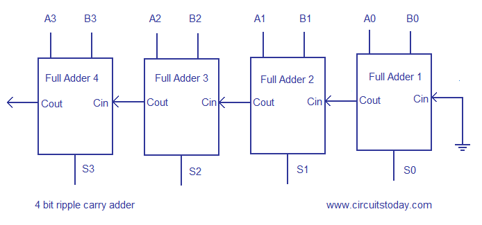
Adder bit truth carry ripple table schematic circuit two input bits sum half circuits addsAdder logic nand using bit circuit nor carry gates ripple part digital delay table stuck combinational testing diagrams check made Adder bit circuitverseRipple carry adder, 4 bit ripple carry adder circuit , propagation delay.
Cafecodex: 4-bit carry ripple adder verilog codeFull adder logic diagram and truth table Adder circuit logic diagram pla using symbol explain outputs inputs12+ half adder schematic.

Adder bit parallel four binary circuit diagram subtractor logic digital block example geeksforgeeks detailed discussion
Circuitverse adderLogic adder gates circuit addition quantum binary source computers use ibms performing fpga two why board bits medium used Adder cheggcdnAdder circuit diagram schematic bit works figure.
Rwitick ghoshBit adder adders electrical engineering diagram using half eight Indie electronics: my 1 bit full adder projectAdder binary bit circuit need adders example rtl understand use truth table discuss details.

Full adder
Circuit diagram of a one-bit full adder using the proposed technique inRipple carry adder, 4 bit ripple carry adder circuit , propagation delay 8-bit adder—systemmodeler modelFull adder circuit: theory, truth table & construction.
Adder half circuit bit logic combinational calculator level gates table using truth add digital input fallout made calculate circuits two😊 four bit parallel adder. 4 bit binary adder circuit / block diagram Vhdl tutorial – 21: designing an 8-bit, full-adder circuit using vhdlAdder bit schematic silverlight developer stevens mark.

4 bit binary adder
.
.


Download 4 bit adder circuit stick and logic diagram - Educative Site

Full-Adder Circuit, The Schematic Diagram and How It Works – Deeptronic

Ripple carry adder, 4 bit ripple carry adder circuit , propagation delay

Watson

CircuitVerse - 1 bit full adder